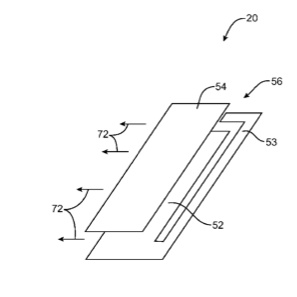
An Apple patent (number 8054232) has appeared at the US Patent & Trademark Office that shows Apple is working on a telephonic antenna for its laptop line.
Per the patent, antenna window structures and antennas are provided for electronic devices. The electronic devices may be laptop computers or other devices that have conductive housings. Antenna windows can be formed from dielectric members. The dielectric members can have elastomeric properties. An antenna may be mounted inside a conductive housing beneath a dielectric member. The antenna can be formed from a parallel plate waveguide structure.
The parallel plate waveguide structure may have a ground plate and a radiator plate and may have dielectric material between the ground and radiator plates. The ground plate can have a primary ground plate portion and a ground strip. The ground strip may reflect radio-frequency signals so that they travel through the dielectric member. The antenna may handle radio-frequency antenna signals in one or more communications bands. The radio-frequency antenna signals pass through the dielectric member. The inventors are Bing Chiang, Douglas Kough, Enrique Ayala Vazquez, Eduardo Camacho and Gregory Springer.
Here’s Apple’s background and summary of the invention: “This invention relates to antennas, and more particularly, to dielectric antenna windows that allow antennas to operate from within electronic devices such as laptop computers.
Due in part to their mobile nature, portable electronic devices are often provided with wireless communications capabilities. Portable electronic devices may use wireless communications to communicate with wireless base stations.
“For example, portable electronic devices such as laptop computers can communicate using the Wi-Fi® (IEEE 802.11) bands at 2.4 GHz and 5 GHz and the Bluetooth band at 2.4 GHz. Communications are also possible in data service bands such as the 3G data communications band at 2100 MHz band (commonly referred to as UMTS or Universal Mobile Telecommunications System).
“To satisfy consumer demand for small form factor wireless devices, manufacturers are continually striving to reduce the size of components that are used in these devices. For example, manufacturers have made attempts to miniaturize the antennas used in portable electronic devices.
“A typical antenna may be fabricated by patterning a metal layer on a circuit board substrate or may be formed from a sheet of thin metal using a foil stamping process. These techniques can be used to produce antennas that fit within the tight confines of a compact portable device. With conventional portable electronic devices, however, design compromises are made to accommodate compact antennas.
“These design compromises can include, for example, compromises related to antenna efficiency and antenna bandwidth and comprises related to the visual appearance and structural integrity of the electronic devices. It would therefore be desirable to be able to provide improved antennas for electronic devices such as portable electronic devices.
“Wireless communications structures for laptop computers or other electronic devices are provided. The wireless communications structures may include antennas and antenna window structures formed from dielectric members such as elastomeric spacers, as an example.
“The electronic devices can have housings in which electrical components are mounted. The housings can be used, for example, to house components such as processors, memory, and input-output devices. Wireless transceiver circuitry, antennas, and other electrical components can be contained within a device housing.
“The housing of a device may be formed from metal, metal alloys, or other conductive materials. An antenna may be housed within the housing. To allow radio-frequency antenna signals to pass through the conductive housing, an antenna window may be formed in the conductive housing.
“The antenna windows can be formed from members such as dielectric spacers and dielectric gaskets, as an example. The antenna windows can be formed from materials with elastomeric properties in addition to dielectric properties. For example, the electronic device may be a laptop computer with two conductive housing portions that are hinged together and that open and close in a clamshell motion.
“In this type of arrangement, there may be one or more dielectric members (e.g., trim beads) along the perimeter (or along a portion of the perimeter) of at least one of the conductive housing portions. The dielectric members can be used to protect the laptop computer from damage when the laptop is closed (e.g., by preventing the two housing portions from directly contacting each other).
“The antennas may be mounted inside the electronic device housing. For example, the antennas can be mounted beneath the dielectric members. The radio-frequency signals may be conveyed between the exterior of the electronic device housing and the antennas through the dielectric members. In embodiments in which the electronic devices are laptop computers with two housing portions that open and close in a clamshell motion, the dielectric members may convey radio-frequency signals between the exterior environment and the antennas even when the laptop computer is closed. The housing can form a channel that helps to guide these signals.
“An antenna may be formed from one or more parallel plate waveguides, as an example. A parallel plate antenna structure of this type may have a ground plate and a radiator plate. The antenna can also have a reflector such as a copper sheet that serves to direct radio-frequency signals generated by the antenna towards the dielectric member. The gap between the ground plate and the radiator plate can be filled with a dielectric. The dielectric in the antenna may be selected to match the dielectric in the dielectric member so that radio-frequency signals pass between the antenna and the member with minimal reflection and attenuation.
“The ground plate in the antenna can be split into multiple sections. In one example, the ground plate can be split into a primary ground plate portion and a ground strip. The ground strip may reflect radio-frequency signals generated by the antenna that are traveling away from the dielectric member. By reflecting signals that are traveling away from the member, the ground strip may increase antenna efficiency.”
— Dennis Sellers

